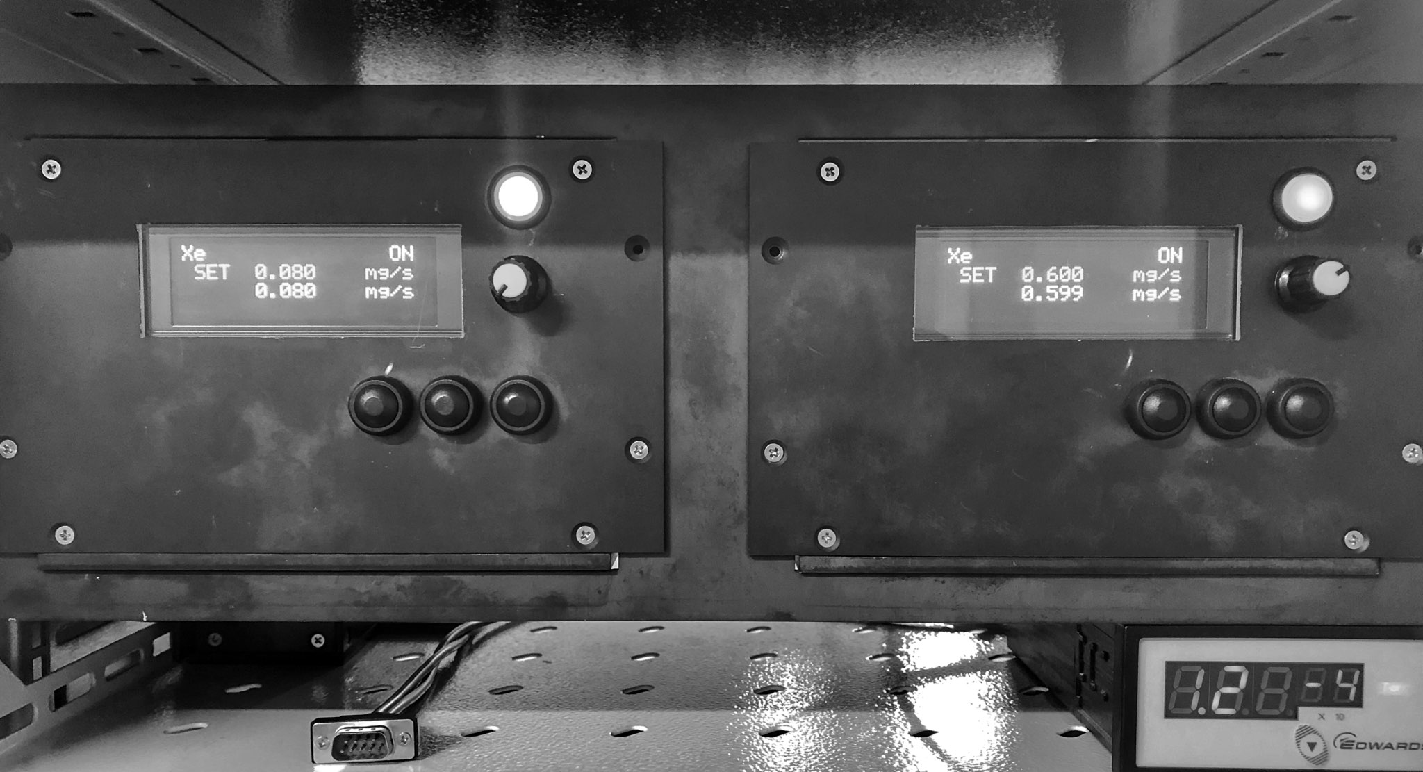
The results of development and calibration of flow rate control units for gaseous propellants (argon, xenon, etc.) for laboratory testing of Hall thrusters are presented. The developed units allow for the independent supply of gaseous working substances to the anode unit and the hollow cathode. The units of flow control are based on the industrial units manufactured by Bronkhorst that can control the flow rate from 0.06 to 2.7 mg/s of argon. The indicators of the flow control units show: the propellant being used, the current flow rate in mg/s, the current in amps equivalent to the flow rate, and the total flow for a given time interval. Accuracy of maintaining the flow rate is 5%. The developed units enable carrying out laboratory tests and adjustment of anode blocks of Hall thrusters of various sizes, as well as hollow cathodes of various designs.
UDK 62-932.2
A.A. ALEKSEIENKO*, A.N. PETRENKO**, V.V. SERBIN*
*Space Electric Propulsion Systems (SETS), Dnipropetrovsk, Ukraine
**Dnipropetrovsk National University (DNU), Dnipropetrovsk, Ukraine
FLOW CONTROLLERS FOR LABORATORY SYSTEM OF STORAGE AND SUPPLY OF PROPELLANT FOR HALL-EFFECT THRUSTERS
Keywords: flow controller, laboratory tests, Hall-effect thruster, anode block, hollow cathode.
Introduction
When conducting laboratory tests and testing the units and subsystems of electric rocket propulsion systems, a laboratory system for storing and supplying the propellant is required, which ensures the supply of a predetermined flow rate of the propellant to the anode block of the Hall engine and the hollow cathode. In the course of testing and tuning of the anode block and the hollow cathode, consumption of the propellant needs to be varied over a wide range of rates.
Classical schemes of gas storage and supply systems for ion thrusters include a tank for storing high-pressure propellant, a reducer, a system of valves and jets providing the required values of the flow rate of the propellant to the anode block and the hollow cathode. The disadvantage of traditional systems of storage and supply of propellant for testing and working out of units and subsystems of electric propulsion systems is the lack of the possibility of independent setting, varying in a wide range and maintaining at a required level the flow to the anode block and hollow cathode.
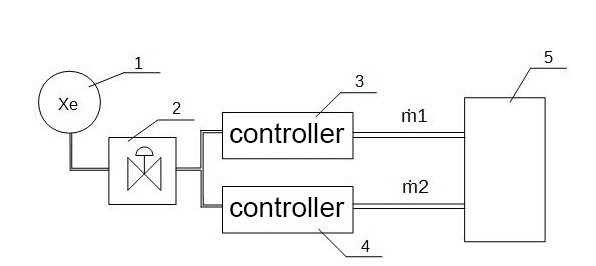
Fig. 1. Flow control diagram.
This disadvantage can be eliminated by creating laboratory gas flow meters with the function of regulation and stabilization of the flow.
Formulation of the problem
The aim is to develop a device for the independent supply of a gaseous propellant to the anode block and hollow cathode of a Hall-effect thruster with the possibility of varying the flow rate and ensuring its stabilization at a required level. In the laboratory studies of the Hall thrusters, various gases (xenon, argon, krypton, etc.) are used, so the laboratory flow controller must be adjustable to a specific gas.
The device should provide the possibility of remote control and information retrieval.
Requirements for the technical characteristics of the device are as follows:
– range of flow adjustment – 0.1 … 5.0 mg/s (xenon);
– number of gas supply channels – one;
– possibility of switching the gas supply on and off;
– availability of data bus, allowing remote control and data collection and recording;
– supplied gas – xenon, or argon, or krypton;
– ensuring stabilization and controlled change of the flow of the supplied gas in the course of experiments;
– indication of the gas in use, the current value of the flow in mg/s, electric current in amps equivalent to the flow, the total value of the gas flow for a given time.
The solution
The traditional scheme of a laboratory system for supplying propellant gas to an experimental propulsion system has two flow channels, as shown in Fig. 1. Such a scheme provides the possibility of independent supply and adjustment of the gas flow to the anode block and the hollow cathode. This allows one to select the optimal operating modes of the anode block and the cathode of a Hall thruster.
In Fig. 1:
1 – a cylinder with high-pressure propellant gas (5-6 MPa);
2 – gas reducer, reducing the gas pressure to the operating value of the inlet pressure of the controller;
3, 4 – flow controllers providing supply of working gas to the anode block (ṁ1) and hollow cathode (ṁ2);
5 – experimental propulsion system.
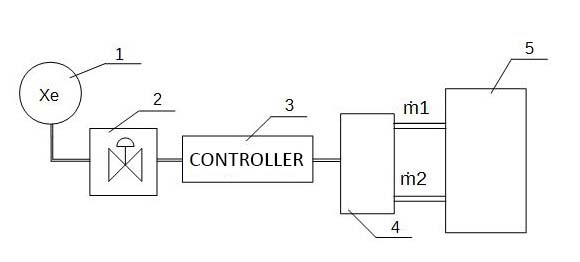
Fig. 2. A single-channel flow controller diagram.
After optimizing the anode block and the hollow cathode of the Hall thruster, the units and elements of the on-board propellant gas supply system are worked out, for which purpose a transition to the structural scheme of the supply system with one flow controller is performed, as shown in Fig. 2.
Fig. 2 shows:
1 – a cylinder with high-pressure propellant gas (5 to 6 MPa);
2 – gas reducer, reducing the gas pressure to the operating value of the inlet pressure of the controller;
3 – flow controller;
4 – a device for proportional distribution of gas between the anode block and the hollow cathode;
5 – experimental propulsion system.
When developing a laboratory flow controller, to reduce the time and costs of development, it is advisable to use the assemblies and blocks of an off-the-shelf controller.
Among the manufacturers of such devices there are companies Sierra, Alicat, Artisan, Bronkhorst, and others.
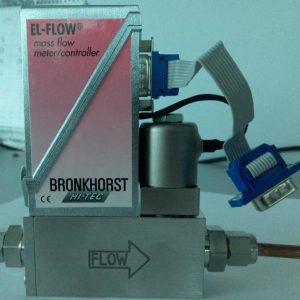
Fig. 3. The unit of a Bronkhorst controller.
The Bronkhorst device, model F-201CV-100-AAD-22-V (Figure 3) was chosen as the basis for constructing the flow controller of the laboratory feed system, the parameters of which correspond most closely to the task set. The chosen device (F-201CV-100-AAD-22-V) has the following parameters:
– primary gas – Ar;
– the minimum flow rate is 0.019 cm3/s;
– The maximum flow rate is 1.39 cm3/s;
– Measurement accuracy – 1% for the range 20 to100%;
– inlet pressure – 1.2 ± 10% Bar;
– the possibility of recalculating the flow rate for other gases (Xe, Kr).
For the operation of the unit, external power supply of 15V is required. The control is carried out by applying a voltage from 0 to 5V, where 0V is a completely cut-off supply, and 5V corresponds to the maximum flow rate. The device provides the measured value of the gas flow in the form of an analog voltage of 0..5 V.
The structural diagram of the developed flow controller can be represented as shown in Fig. 4:
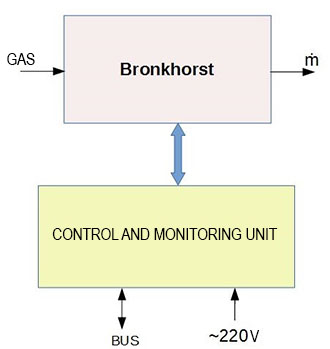
Fig. 4. Structural diagram of the gas flow controller.
Bronkhorst – measuring and actuating device of the flow regulator;
Control and management unit – includes power supply unit, calculator and other systems for working with the Bronk-horst device.
In the functional diagram (Fig. 5), the controller device is shown more detailed.
Bronkhorst (block A1) is connected to our circuit via a connector, through which it receives power and control, and returns a signal corresponding to the measured flow. The blocks A5, A8, A9, A13 form the supply and service (Vref) voltages necessary for the operation of the regulator. As a microcontroller, a chip of AVR series produced by Atmel. It has an 8-bit architecture, and does not feature floating-point calculations; therefore, integer arithmetic is used. This allows us to make sufficiently rapid calculations of the values displayed by the flowmeter.
The use of integer arithmetic also required the use of 12-bit ADCs (block A2) and DAC (A4). Their increased bit width enables compensation the loss of accuracy in the calculations to a level below the accuracy of the Bronkhorst meter.
To set parameters and control the flow meter operation, mechanical buttons and an encoder (block A6) are used.
For easy reading of information, the OLED display (block A3) is used. It has good brightness and high contrast, which are characteristic of this type of display.
The bus for remote control and information retrieval is implemented as an RS-485 interface. The units A10, A11, A12, A14, A15 provide electric potential level conversion and galvanic isolation between the bus (RS-485) and the microcontroller (UART).
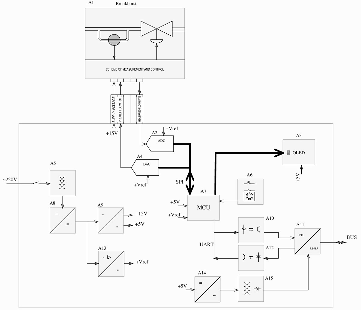
Fig. 5. Functional diagram of the gas flow controller.
Conclusions
After the development and manufacture of several copies of the flow regulator, a scatter was observed in maintaining the flow between the specimens. The spread reached 10%. This required calibration of flow regulators. As a sample gas for calibration, argon was used. The calibration was carried out by a displacement method. As a result of the calibration, the accuracy of maintaining the propellant gas flow rate is not worse than 1%.
Thus, analyzing the results obtained, we can draw the following conclusions:
– the use of the off-the-shelf blocks has made it possible to significantly reduce the time and cost of developing and manufacturing laboratory gas flow regulators;
– calibration of the regulators provides the accuracy of maintaining the flow required for conducting laboratory tests of electric rocket engines;
– The developed device makes it possible to easily switch from one propellant gas to another by programmatically switching the constants determined for each gas used as propellant.
Thus, the laboratory flow regulator enables determination and optimization of the working processes of supplying propellant gas to electric rocket engines in order to obtain recommendations on the design of on-board supply systems, as well as the development of algorithms for the on-board control system of an electric rocket propulsion system.
References
Datasheet F-201CV Mass Flow Controller for Gases. http://www.bronkhorst.com/files/downloads/datasheets/el–flow/f-201cv.pdf .
- Архипов, Б.А Опыт создания полых высокоэмиссионных катодов. [Текст]/ Архипов Б.А., Мурашко В.М., Оранский А.И. // Авиационно-космическая техника и технология. -1999. -№.10 – С. 360-363.
- Хитько, А.В. Ампульный источник плазмы/А.В.Хитько// Проблемы управления и информатики.-2003.-№6-С.101-105.
Reviewer: Dr. tehn. Sciences, N.M. Drone, Oles Honchar Dnipropetrovsk National University, Dnepropetrovsk.


