The structure of electric propulsion systems based on Hall thrusters includes an energy processing and control unit (PPU) that converts the electrical energy of an onboard power supply into the voltages and currents needed to operate of all the propulsion system subsystems. One of the main secondary power supplies of PPU is the discharge power supply, the parameters of which largely determine the parameters of PPU and the entire electric propulsion system. There are the results of the development of a high-efficiency discharge power supply for the Hall thruster ST-40, which is as component in the warehouse of the electric propulsion system SPS-40 in this article. At the discharge power supply developing, it must be taken into account that during of the Hall thruster start the big of voltage and current surges existing, that is why it’s too difficult for the discharge power supply can be operated with high efficiency (93 – 95%). When choosing of the power supply principle of operation, its functional and structural scheme, it was proposed to provide stabilization of the supply output power by introducing appropriate feedbacks. The article presents the functional and structural diagrams of the discharge supply, which provides stabilization of a given value of the output power of the discharge supply. Laboratory tests of the developed discharge power supply with active load showed that the technical solutions adopted during the development process provided the possibility of stabilizing the output electric power of the supply at a given level – 200 and 400 W. The use of an electric power stabilizer as a discharge power supply for the ST-40 Hall thruster made it possible to obtain a high value of the supply efficiency (more than 93%) in a wide range of discharge voltage and current. Laboratory tests of the developed discharge supply together with the ST-40 Hall thruster showed that the thruster, after the hollow cathode temperature reaches a predetermined value, starts reliably and works stably after starting.
Keywords: electric propulsion system, Hall thruster, discharge power supply, +, Hall thruster testing
Introduction
The development of the electric propulsion systems (EPSs) based on the Hall thruster necessitates the development of highly efficient power supplies that are components of the power processing unit (PPU) in structure of EPS.
This unit converts the electrical energy of an on-board power source into voltages and currents that ensure the operation of all EPS subsystems. PPU consists of the following power supplies: discharge power supply, supply for the ignition electrode, power supply for electromagnets, preheating of the hollow cathode, and a source that ensures the functioning of the Xenon storage and feed system of the working substance for the Hall thruster. The PPU also includes a propulsion system control unit, which provides the receiving of EPS control signals from the spacecraft control system and the creation of control signals for all controlled secondary power supplies of the PPU.
The high requirements for mas and size characteristics, efficiency, stability and reliability of electric propulsion system on-board power supplies are existed. In some cases, the mass and dimensions of PPU are at least 40–50% of the entire electric propulsion system, and the requirements for the efficiency of power supplies exceed 93–95% [1, 2].
The discharge power supply, which is part of the PPU of a propulsion system with Hall thruster, has the maximum mass and dimensions compared to other secondary power supplies. Therefore, optimization of the discharge power supply leads to a significant improvement in the parameters of not only the PPU, but of the entire electric propulsion system as a whole.
Goals and objectives of the investigation
An actual in the design and development of the PPU of an electric propulsion system with a Hall thruster is the search for such options for constructions of a power source for the discharge circuits of the Hall thruster that ensure reliable start-up of the thruster and its stable operation in predetermined modes while ensuring high efficiency, stability and reliability values.
It’s well known [1] that at the moment of the Hall thruster starting significant discharge currents occur (over 250 – 300 μs), which necessitates the use of a discharge power supply that significantly exceeds the rated mode in power. All this leads to a significant increase in the mass and dimensions of the discharge power supply for Hall thruster.
The aim of this research was to select such a structure and parameters of a secondary discharge power source for a Hall thruster, which would provide high efficiency, stability and reliability of the supply operation together with the thruster.
To achieve this goal, it was necessary to solve the following tasks:
- choose a block diagram of the discharge power supply;
- develop a functional diagram;
- make a choice of the component base, which in its characteristics and parameters corresponds to the component base for space applications;
- conduct autonomous tests of the developed discharge power supply using active load;
- conduct laboratory tests of the discharge power supply in conjunction with the Hall thruster.
The choice of structural and development of functional schemes of the supply
The main requirements for the discharge power supply for the Hall thruster are determined by the characteristics and parameters of the thruster, as well as its operating modes. From these requirements, the structural and functional diagrams of the discharge power supply follow.
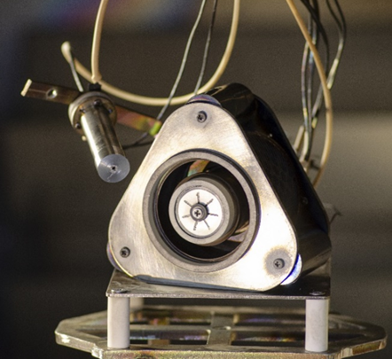
The SPS-40 electric propulsion system, developed by Space Electric Thruster Systems (SETS), incorporates the ST-40 Hall thruster with a power consumption of 300 – 500 W. The appearance of ST-40 Hall thruster is shown in Fig. 1, and its main parameters are presented in Table. 1.
| N | Thruster’s parameters | Value |
| 1 | Input power, W | 300 – 500 |
| 2 | Discharge voltage, V | 200 – 300 |
| 3 | Discharge current, A | 1.2 – 2.2 |
| 4 | Ignition power, W | 55 – 60 |
| 5 | Ignition voltage, V | 1200 |
| 6 | Main (anode) mass flow rate, mg/s | 1.3 – 2.3 |
| 7 | Cathode mass flow rate, mg/s | 0.1 – 0.2 |
| 8 | Electomagnet current, A | 1.0 – 2.1 |
| 9 | Thrust, mN | 14 – 35 |
For the full version press the link
& ask your question at comments below


