In the article results of development and experimental tests of Hall-effect Thruster ST-25 are presented. This thruster is intended for application on small space vehicles. With the purpose of decrease of input electric power in the magnetic system of the thruster a permanent magnet is applied. The permanent magnet is located at the base of the central magnetic core. The permanent magnet provides most of the magnetic induction in the accelerating channel of the thruster, while the side magnets provide precise magnetic field adjustment. Laboratory testing of the ST-25 thruster was realized with application of the preheated hollow cathode which is operated in auto mode at the discharge current 0.5 … 0.9 A. In the process of developing the thruster, its laboratory tests were carried out with a laboratory prototype of the Xenon system for storing and supplying a working substance. The laboratory supply system provided the supply of the working gas to the anode unit 0.65 … 0.90 mg /s and 0.07 … 0.10 mg / s to the hollow cathode. The characteristics and parameters of the thruster were obtained using a discharge power supply that has the properties of a voltage source and a power source. The discharge power supply is the part of the flight prototype of the power processing unit. Laboratory tests have confirmed the rightness of the technical decisions stopped up in the structure of the thruster. Methodology of the thruster ST-25 start at the use of preheated cathode and flying prototype of the discharge power supply were improved. Possibility of application of such type of Hall Thrusters on space vehicles with the size of on-board electric power of that is limited to the size 200 – 300 W were confirmed.
Keywords: hall-effect thruster, magnetic system of hall thruster, permanent magnet, laboratory tests of the hall thruster, flying prototype of the electric power supplies, discharge voltage stabilization, discharge power stailization, parameters of the hall-effect thruster.
Introduction
Electric propulsion thrusters (EPT) are widely used on spacecraft vehicles (SC) for solving the problems of orientation and stabilization, maintaining and changing the parameters of the orbit, deorbiting the SC after the end of the mission.
The most widely used EPTs are the M-70 and SPT-100 thrusters, developed by EDO “Fakel” (Kaliningrad, Russia). These thrusters have a power consumption of 660 – 1200 W and are used on spacecraft that have a sufficient amount of electrical power on board.
At the same time, the current stage of space technology development is characterized by a significant decrease in the spacecraft mass, as a result of which the level of electrical energy on board the spacecraft does not exceed 400 – 500 W, and no more than 200 – 300 W of electrical power can be allocated for electric propulsion thrusters.
Formulation of the problem
Design of the electric propulsion thruster with power consumption in the range 200 – 300 W. Laboratory testing of designed thruster at two regimes of the discharge power supply operating а) with discharge voltage stabilization; b) with discharge power stabilization. To determine the main static characteristics of the thruster for both regimes of the discharge power supply operation. As results of the thruster laboratory testing to determine the optimal regimes of the electric propulsion thruster operation.
Solution of the problem
For solution of the electric propulsion thruster design with small power consumption for small spacecraft one of the Hall-effect thruster variant was chosen. That is Hall-effect thruster with the insulator accelerating channel, in which axial electric and radial magnetic fields were realized – ST-25.
Specific of the ST-25 structure is using the permanent magnet in central core for decreasing electrical power for creation the radial magnet field in the thruster acceleration cannel. The permanent magnet is manufactured from material SmCo, point Curie of which is in the range 810 … 900°С, that is why such magnet can be used at the working temperature about 350°С. As outer electromagnets four traditional electromagnet are used. The stable current for these electromagnets is used from separate power supply. Structure scheme of the ST-25 thruster (without hollow cathode) is presented in Fig.1.
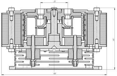
ST-25 thruster consists of annular discharge channel and magnetic system which create the radial magnet field. Working substance (Xenon) is fed into Anode which is located at the acceleration channel bottom. An arc discharge is created between Anode and outer hollow cathode in the acceleration channel. Ions, which are born as result of arc discharge in acceleration channel, are accelerated by axial electrical field. The flow of accelerated ions is neutralized by electrons which are moved from hollow cathode. In this way behind the thruster cut the neutral atoms flow of working substance is forming which determined the value of the thrust.
For the ST-25 thruster the preheated hollow cathode was designed and developed. It insures keeping arc discharge in the thruster acceleration channel and neutralization of the ion beam. The hollow cathode working current which keeps auto regime operation is 0,6…1,0 А, the value of the hollow cathode mass flow rate is in the range 0.06…0.10 mg/sec.
Laboratory testing of the thruster
ST-25 thruster laboratory testing was carried out in the testing laboratory of SETS (Dnipro, Ukraine) using the experimental facility, consists of the vacuum chamber, laboratory storage and feed system, flight prototype the power processing unit, and laboratory instrumentation rack. The general view of the experimental facility is presented in Fig. 2.
The vacuum chamber is equipped by turbomolecular pump, which provides the vacuum 1·10-6 Tor at absence of the working gas mass flow rate and value 2·10-4 Tor at the maximal mass flow rates into anode and hollow cathode. Inside of vacuum chamber the devise for measurement of the thrust level is located. This devise can be used for measurement of the thrust in the range 0.0 … 20.0 mN. The error of the thrust measure is about ± 5% from maximal value.
Laboratory Xenon storage and feed system (XFS), which was used for feeding the working gas into anode unit and hollow cathode. It consists of the tank with Xenon, the reducer, manometer, and devices of control and measurement the mass flow rate (Fig. 2). Referenced values the mass flow rates into anode unit and hollow cathode are determined by devices F-201CV Bronkhorst company.
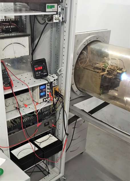
Figure 2 – General view of the experimental facility for ST-25 testing 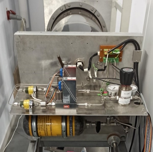
Figure 3 – Laboratory storage and feed system
Flight prototype the power processing unit for ST-25 thruster (PPU) includes the power supplies: discharge, electromagnet, heater and keeper of cathode and also supplies insured the storage and feed system operation. Electrical scheme connection ST-25 thruster to power processing unit and XFS is presented on Fig. 4.
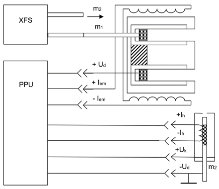
Figure 4 – Scheme connection ST-25 thruster to power processing unit
On this figure such notations are used:
Ud – discharge voltage;
Iem – electromagnet current;
Ih – current of the cathode heater;
Uk – voltage of the cathode keeper;
m1 – mass flow rate into anode unit; m2 – mass flow rate into hollow cathode.
Laboratory testing of the thruster was carried out in two stage. At the first stage ST-25 thruster was tested with the discharge power supply operating in regime discharge voltage stabilization; electromagnet current supply and voltage supply of the keeper hollow cathode.
During the first stage of testing following characteristics of the thruster were determined: dependency the thrust from discharge voltage and discharge power at the fixed levels of the anode mass flow rate; the thrust from anode mass flow rate at fixed levels discharge voltage and also the value of specific impulse from discharge voltage.
Discharge voltage was changed in the range 150 … 250 V; mass flow rate into anode unit was changed in the range 0.5 … 0.9 mg/s; mass flow rate into hollow cathode was kept at level 0.07 mg/s: discharge power in anode unit was changed in the range 70 … 270 W. The graphs of the obtained characteristics of the ST-25 thruster at using discharge power supply with voltage stabilizing are presented on Fig. 5 – Fig. 8
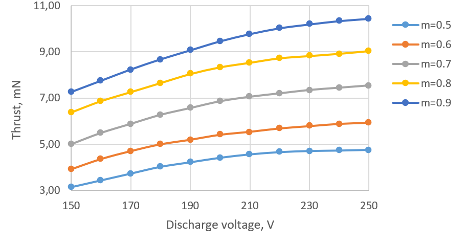
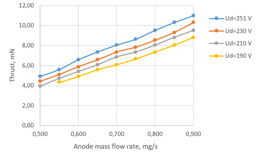
Figure 5 – Dependence of the thrust from discharge voltage (left)
Figure 6 – Dependence of the thrust from mass flow rate into anode unit (right)
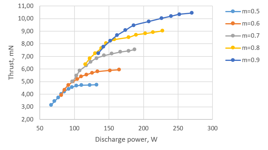
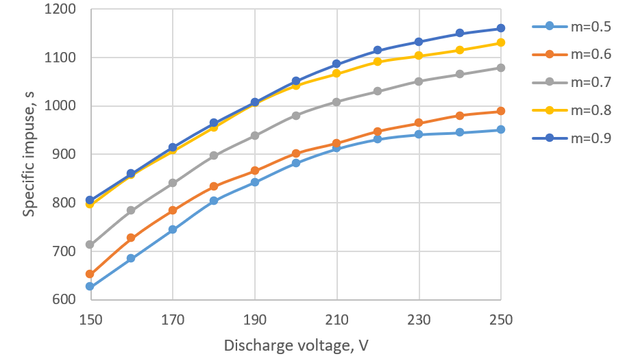
Figure 7 – Dependence of the thrust from discharge power (left)
Figure 8 – Dependence of the specific impulse from discharge voltage (right)
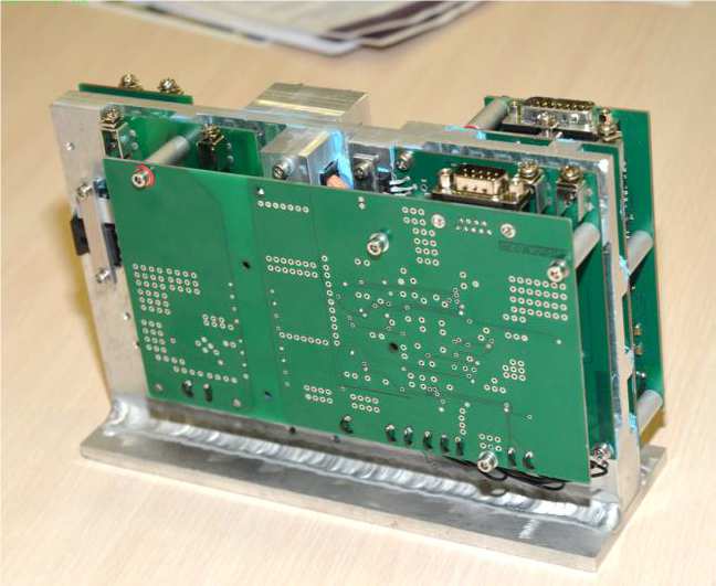
It’s known, the Hall-effect thruster parameters and characteristics which are obtained with using the discharge voltage supply can be strongly differenced from parameters and characteristics obtained with using the discharge power supply. That is why during the second stage of the ST-25 testing flight prototype the discharge power supply was used. This discharge power supply is as component of the PPU flight prototype and insures the discharge power stabilizing. General view of the discharge power supply which was used during the second stage the thruster testing is presented in Fig. 9. General technical parameters of this discharge power supply are presented in Table 1.
| Parameters | Value |
| Input voltage, V | 20…36 |
| Maximal input power, W | 400 |
| Maximal discharge power, W | 300 |
| The range discharge voltage, V | 50…400 |
| Regimes of stabilizing | Voltage/Power |
| Efficiency, % | >95 |
| Mass, kg | 3.5 |
| Dimensions, mm | 220x150x75 |
Table 1 – Parameters of the discharge power supply flight prototype
In results of the ST-25 thruster testing using discharge power supply insured discharge power stabilizing dependences the thrust from anode mass flow rate and discharge power; the specific impulse and efficiency values from disgorging power are obtained. The graphs of correspondent experimental dependencies are presented in Fig. 10 – Fig. 13.
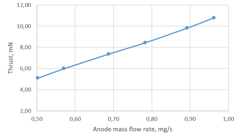
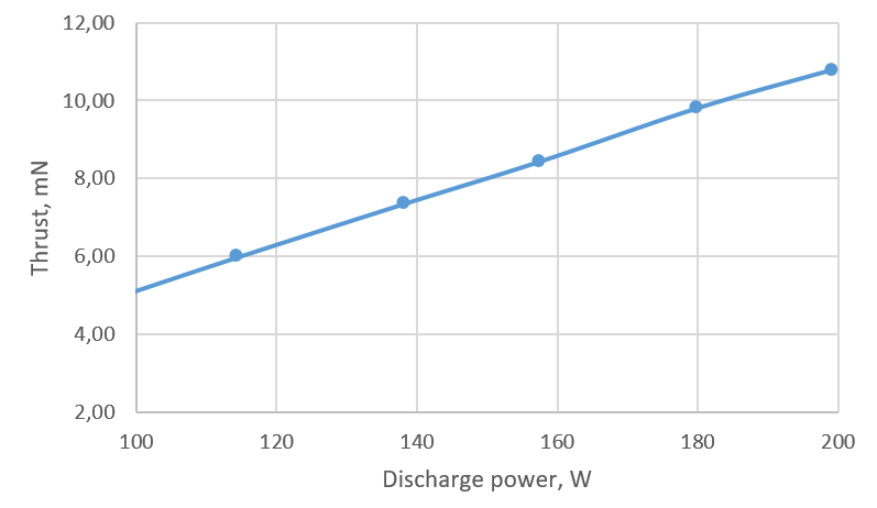
Figure 10 – Dependence of the ST-25 thrust from anode mass flow rate at the discharge power stabilizing (left)
Figure 11 – The dependence of the ST-25 thrust from the discharge power (right)
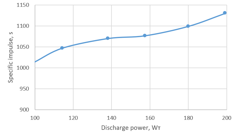
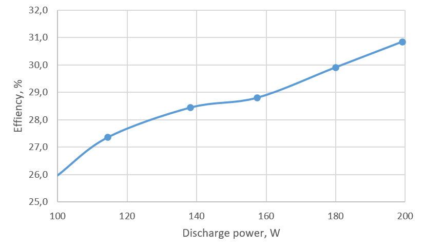
Figure 12 – The dependence of the ST-25 specific impulse from discharge power (left)
Figure 13 – The dependence of the ST-25 efficiency from discharge power (right)
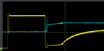
Figure 14 – Typical cyclogram of the ST-25 starting
In frame of the ST-25 laboratory testing alongside with the static characteristics determining the cyclogram of the thruster starting was developed. Typical cyclogram of the thruster starting is presented in Fig. 14.
CONCLUSIONS:
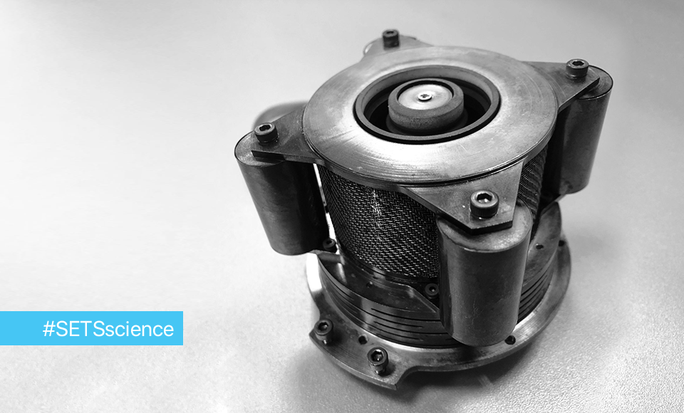
- In result of this work Hall-effect thruster with permanent magnet was designed, manufactured, and tested. The main parameters of the designed thruster are presented in Table 2, general view is presented in Fig. 15.
- The laboratory testing improved efficiency of application in magnetic system structure the permanent magnet. In result, the level of electric power for radial magnetic field creation was significantly decreased.
- Experimental characteristics and parameters of the ST-25 thruster were obtained by using the laboratory power supplies which have proprieties of flight prototypes.
- The methodic of the thruster with preheated cathode starting was designed and developed.
- As result of ST-25 thruster testing, it was improved the possibility of application
- such type of the thruster onboard spacecraft in which primary power less than 300 … 500 W.
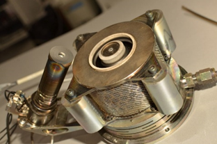
Figure 14 – General view of the ST-25 thruster with hollow cathode
| Parameters | Value |
| Input power, W | 150…200 |
| Discharge voltage, V | 200…260 |
| Electromagnet electric power, W | < 10 |
| Power of cathode heater, W | < 50 |
| Anode mass flow rate, mg/s | 0.65…0.90 |
| Cathode mass flow rate, mg/s | 0.07…0.10 |
| Thrust, mN | 7…11 |
| Specific impulse, s | < 1200 |
| Thrust efficiency, % | < 30 |
| Cost of the thrust, W/mN | 19…21 |
| Mass of the thruster (with one cathode), kg | 0.75 |
| Dimensions (without cathode), mm | 79x79x79.5 |
| Lifetime (estimation), hr. | 3000 |
Table 2 – Characteristics of ST-25 thruster


